Induction looper: Difference between revisions
No edit summary |
|||
| Line 42: | Line 42: | ||
[https://signet-ac.co.uk/other/REV%202%20AFILS%20GUIDE%20%20AG.pdf SigNET. (2011). A Guide to Audio-Frequency Induction Loop Systems.] | [https://signet-ac.co.uk/other/REV%202%20AFILS%20GUIDE%20%20AG.pdf SigNET. (2011). A Guide to Audio-Frequency Induction Loop Systems.] | ||
[https://signet-ac.co.uk/other/SIGNET_AFILS_GUIDE_DML0540000_rev1%20(1).pdf SigNET. (2014). A Guide to Audio-Frequency Induction Loop Systems [rev1].] (newer version with crappier layout) | |||
[https://signet-ac.co.uk/other/SIGNET_AFILS_GUIDE_DML0540000_rev1%20(1).pdf SigNET. (2014). A Guide to Audio-Frequency Induction Loop Systems [rev1].] | |||
== Electronics == | == Electronics == | ||
Revision as of 14:11, 25 February 2020
| Project Induction Looper | |
|---|---|
| |
| Induction Loop audio on the cheap and easy | |
| Status | In progress |
| Contact | Sebastius, Pwuts, Noor |
| Last Update | 2020-02-25 |
Plan is to make a really cheap and really portable induction loop system that we can just give to conferences for free. That will enable them to help hearing impaired visitors listen in to talks via the t-coil in their hearing aids. Sidequests include using these systems to create secret audio spots for quests and other stuff.
Original inspiration for the project: A DIY Audio Induction Loop for the Hard of Hearing - IEEE Spectrum.
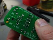
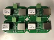
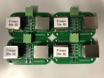
Sebastius designed a little board that allows configurable amount of loops. Prototypes have fixed settings, switches are still underway from China.
Board files: https://github.com/sebastius/inductionlooper
First test was very successful!
Loop placement
If the signal must be received in a certain space, one can make two loops at any two opposing ends (and maybe one in the middle if the other two are at the short ends) or one loop around the whole room. To get an idea of signal distribution and decay, use this: https://www.falstad.com/vector3dm/ ("current loop", "loop pair stacked", "rectangular loop").
People with hearing aids can't be expected to stay stationary which must (I think) be reckoned with for signal distribution and thus placement of the loops.
As for the induction loops themselves: less windings/turns is generally better for signal quality, because impedance at high frequencies increases with n^2, while the required current for equal signal strength only decreases 1/n so effectively the required voltage for the same signal strength (at higher frequencies) increases with n. This is important because higher frequencies are critical for identifying most consonants.
Calculator for rectangular loop inductance
Induction loop system calculator by Signet (xls, works in Libre)
SigNET. (2011). A Guide to Audio-Frequency Induction Loop Systems.
SigNET. (2014). A Guide to Audio-Frequency Induction Loop Systems [rev1.] (newer version with crappier layout)
Electronics
For the driving electronics, there are basically two options:
- using a regular audio amplifier and matching the impedance of the adjusted loop so the amplifier doesn't shit itself
- building a transconductance amplifier and optimize the loop for low impedance
We could also spend €400 on a professional induction loop driver but until now that hasn't come to the table as an option, probably also because this is intended to be accessible so that it can be used at smaller events and spaces as well. Using an expensive amplifier would defeat that purpose entirely.
Using a regular audio amp
This is, in terms of electronics, the easiest way. It requires an amplifier (of course) and a loop with 8 ohms of impedance.
Transconductance amplifier
This is how it's done professionally. A circuit that takes voltage at the input and outputs a current proportional to the input voltage.
After some searching it seems Ali doesn't have them, so this is going to be a DIY board.
Making a simple half-wave transconductance amplifier isn't that complicated. It's the sensible (additional) requirements that have potential to make it complicated:
- it needs to output both the positive and negative halves of the signal, not just the positive half
- volume control would be nice
- pls no EMPs when turning it on
But, set aside the above requirements, the minimum can be achieved with an OP-AMP, a FET or BJT and a resistor [example]. Because of the OP-AMP this is called an Operational Transconductance Amplifier (OTA).
Class A/B
Building a Class A or Class B amplifier is probably the cheapest when it comes to the BOM, but may be more complicated in terms of design and usage conditions.
The simplest would be a Class A OTA, with one MOSFET or BJT doing the hard work. To get more than just the half-wave signal, the output signal either has to be shifted so it is enterely positive, or a second, negative power supply rail is needed. The need for a symmetrical power supply would make this whole thing significantly less accessible or easy to implement. But shifting the signal upward by one amplitude means that for zero input, there will be a static output, wasting power and creating a static magnetic field.
An example of a relatively simple Class A-ish OTA (©®Pwuts™2020)
To solve the dilemma mentioned above, a Class B OTA can be built instead. It uses two transistors, allowing the direction of the current to be reversed and thus eliminating the idle current. This does need more tuning though, as the (in this case MOSFE)T will go into saturation more quickly than the one in the Class A due to the different configuration. This would cause clipping. Carefully chosen transistors or high supply voltage can be solutions.
An example of a Class B(oat) OTA
As an extra, I experimented a bit with a Class AB configuration and with BJTs instead of MOSFETs (like in the Class B). The class AB config works pretty well, and eliminates the crossover noise the Class B outputs. Using BJTs has the advantage that the output stage doesn't generate high frequency ripples when oversteered as far as I can tell.
Currently trying to figure out how to make this more efficient, as about 6Wp (2.12W RMS total) is dissipated in the transistors per Ampère of output current.
Class AB with BJTs and better input filtering
Power OP-AMP
Using a power OP-AMP like the LM675 would make this a lot easier, as there is only one active building block for the amplifier (the OP-AMP itself). To build a transconductance amplifier, the feedback network has to be made so that the feedback to the V- of the OP-AMP is proportional to the current in the load (or in this case, the loop). This isn't very hard to do and can also easily be fitted with volume control, see the example below.
OP-AMPs also normally need positive and negative power supply, but their voltage supply is differential so it's also possible to supply it with e.g. +24V (Vcc) and 0V instead of +12V and -12V.
To make this work, a second supply voltage will be needed, of Vcc/2. This will be used to shift the level of the OP-AMP's input and feedback network, and can also be used to shift the output current back to zero equilibrium (the source needs to be able to handle negative current for this).
An example of a power-OP-AMP OTA with volume control and single sided power supply
Testing: Telecoil receiver?
With some help of Benadski I (Pwuts) changed a capacitor on the EM sniffer so it's better suited for listening to low frequencies. As a result I could actually hear the transmitted sound over the EM noise coming from the wall. It's still not really an induction loop tester though, so I would advise against using it as some kind of reference.
