TIX clock: Difference between revisions
| Line 37: | Line 37: | ||
== Software == | == Software == | ||
Github archive for | Github archive for the software prototype is at https://github.com/bertrik/esptixclock | ||
My plan (bertrik) is to re-use the code from the [Lichtkrant], adapt it for ESP32 (instead of ESP8266). | |||
It uses essentially the same concept, except with 3 rows / 9 columns instead of 7 rows / 80 columns. | |||
Basic principles: | |||
* Basic ESP32 framework with simple command interpreter. We need ESP32, because the ESP8266 is short on pins (we need at least 12: 9 columns, 3 rows). | |||
* TIX display driver that alternates between rows and lights up the pixels in the columns | |||
** implement dimming, because we can | |||
** run it at a much higher framerate, the ESP32 is faster anyway and we have fewer pixels | |||
* NTP client to get UTC time from NTP + local time conversion (incl. summer time) | |||
* Main process to convert local time into TIX format (number of LEDs lit in a group indicates number) | |||
** Maybe some nice animation on startup. | |||
Framerate calculation: | |||
Suppose we have 4 rows (3 actual + 1 "vsync" row), 4-bit intensity (16 levels) and at least 100 Hz updates, we need 4x16x100 = 6400 line rate. | |||
Rounded up to 10000 Hz interrupt rate, this means that the worst case flicker is 156 Hz. | |||
If this is still too low in practice, we can reduce the dimming resolution, or just use the LEDs at full brightness. | |||
In comparison, a MAX7219 has a "scan-rate" of 800 Hz typically. | |||
==Timeline== | ==Timeline== | ||
Revision as of 12:24, 20 January 2020
| Project TIX clock | |
|---|---|
| |
| Status | In progress |
| Contact | Noor, bertrik |
| Last Update | 2020-01-20 |
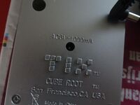
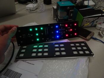
Have an 'original' TIX clock (YouTube video) from ThinkGeek.
Could also be programmed to display any number up to 4 digits, but the design is best suited for displaying time (blocks are in sets of 3, 9, 6, 9).
Reverse engineering
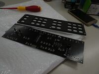
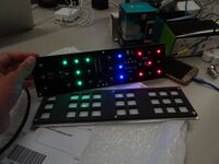
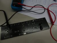
There are a total of 27 LEDs on the board, organised as 9 columns of 3 leds each. Each column has a shared cathode.
There are a total of 19 transistors on the board. Each column has its own transistor.
From left to right:
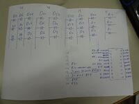
- column: D27/D18/D9, cathode connected through 62 ohm to collector of Q11, which is controlled through 220 to IC pin 5 (RBx?)
- column: D26/D17/D8, cathode connected through 62 ohm to collector of Q12, which is controlled through 220 to IC pin 6 (RB0)
- column: D25/D16/D7, cathode connected through .. to collector of Q13, which is controlled through ... to IC pin 7 (RB1)
- column: D24/D15/D6, cathode connected through .. to collector of ..., which is controlled through ... to IC pin 9 (RB3)
- column: D23/D14/D5, ... IC pin 10 (RB4)
- column: D22/D13/D4, ... IC pin 11 (RB5)
- column: D21/D12/D3, ... IC pin 12 (RB6)
- column: D20/D11/D2, ... IC pin 13 (RB7)
- column: D19/D10/D1, ... IC pin 15 (RA6)
Rows:
- D27/D26/D25/D19, D24/D23, D22/D21/D20
- D18/D17/D16/D10, D15/D14, D13/D12/D11
- D9/D8/D7/D1, D6/D5, D4/D3/D2
D13 cathode goes to D12 cathode, goes to Q5 collector, Q5 base goes to R5, R5 goes to
Software
Github archive for the software prototype is at https://github.com/bertrik/esptixclock
My plan (bertrik) is to re-use the code from the [Lichtkrant], adapt it for ESP32 (instead of ESP8266). It uses essentially the same concept, except with 3 rows / 9 columns instead of 7 rows / 80 columns.
Basic principles:
- Basic ESP32 framework with simple command interpreter. We need ESP32, because the ESP8266 is short on pins (we need at least 12: 9 columns, 3 rows).
- TIX display driver that alternates between rows and lights up the pixels in the columns
- implement dimming, because we can
- run it at a much higher framerate, the ESP32 is faster anyway and we have fewer pixels
- NTP client to get UTC time from NTP + local time conversion (incl. summer time)
- Main process to convert local time into TIX format (number of LEDs lit in a group indicates number)
- Maybe some nice animation on startup.
Framerate calculation: Suppose we have 4 rows (3 actual + 1 "vsync" row), 4-bit intensity (16 levels) and at least 100 Hz updates, we need 4x16x100 = 6400 line rate. Rounded up to 10000 Hz interrupt rate, this means that the worst case flicker is 156 Hz. If this is still too low in practice, we can reduce the dimming resolution, or just use the LEDs at full brightness. In comparison, a MAX7219 has a "scan-rate" of 800 Hz typically.
Timeline
2019-11
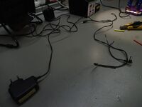
Changed out the American plug for an EU one, but the clock requires 60 Hz AC, and 50 Hz will make it run slow and thus useless for telling time.
2020-01-17 - 2019-01-20
From an old Tweakers thread: "Dus schoef je wekker eens open en google op het typenummer van de chip. 10 tegen 1 dat er een 60/50Hz-select pootje aanzit. Vaak is die verbonden met een draadbruggetje op de print; omsolderen en klaar!"
Looked into this but no luck. Best bet is to replace the chip (original PIC16F628A, with ESP8266?) and update time via wifi.
