EspAudioSensor: Difference between revisions
No edit summary |
|||
| Line 11: | Line 11: | ||
The plan is to do this by combining an inexpensive WiFi-enabled ESP-32 microcontroller with a standard I2S digital microphone. | The plan is to do this by combining an inexpensive WiFi-enabled ESP-32 microcontroller with a standard I2S digital microphone. | ||
Another idea: | |||
* implement basic speech recognition of fixed phrases, like "ok google", "hey siri" | |||
== Measuring audio as a citizen science project == | == Measuring audio as a citizen science project == | ||
Revision as of 15:08, 25 April 2019
| Project ESP audio sensor | |
|---|---|

| |
| ESP-based audio sensor | |
| Status | In progress |
| Contact | bertrik |
| Last Update | 2019-04-25 |
Introduction
This project is about creating an audio level meter, for example as an environmental noise measuring node in a citizen science project or as a standalone "decibel meter".
The plan is to do this by combining an inexpensive WiFi-enabled ESP-32 microcontroller with a standard I2S digital microphone.
Another idea:
- implement basic speech recognition of fixed phrases, like "ok google", "hey siri"
Measuring audio as a citizen science project
The idea is the following:
- A small box containing a microphone outside your house measures environmental sounds (traffic, etc), for example it takes a 1 second audio recording every 10 seconds
- A spectral analysis is made of the audio (separating it in different frequency bands), calculating sound intensity for each individual band
- Every 5 minutes, the measured sound intensity is sent to a central server on the internet using your home WiFi connection. Because we only communicate intensities, this does not reveal audio fragments (conversations for example).
- The central server takes the measured intensities and can do corrections, like a microphone specific correction, or a correction to apply A-weighting
- The central server visualises the measurements:
- We can plot the sound intensities on a map as a coloured dot and get a nice overview how the map changes during the day/week/year
- We can plot the sound intensities of individual nodes vs time, and get an idea how sound varies from day/night/week/year
External things to investigate:
Theory
The plan is to divide the audio spectrum up into octaves and calculate the total energy in each octave. We can then easily apply sensor/housing specific corrections, do A weighting, etc.
Subjective audio levels are generally calculated on a logarithmic scale in dB using "A-weighting". A-weighting calculates a subjective loudness level from a physical loudness, applying a correction factor for each band. The division of the audio spectrum is chosen so it matches the octaves used in the A-weighting, see https://en.wikipedia.org/wiki/Octave_band#Octave_Bands
FFT
The energy in each octave is calculated by applying an FFT (fast fourier transform) on the audio data. The FFT takes in real values and outputs complex values. The intensity in each octave band is by summing the energy in a set of FFT 'bins'. The energy in each bin is calculated as the real part squared plus the imaginary part squared.
Links:
- Overview of octave bands https://www.engineeringtoolbox.com/octave-bands-frequency-limits-d_1602.html
- http://www.robinscheibler.org/2017/12/12/esp32-fft.html
Decibel meters
Commercially available meters:
Fairly typical specs:
- dynamic range: 30 - 130 dB
- accuracy: 1.5-2 dB
- frequency range: 31.5 Hz - 8 kHz (!)
- norm: EN 61672-1
Hardware
The physical device consists of:
- an ESP32 (or possibly an ESP8266), it has an I2S digital audio input for sampling data from a digital microphone and a WiFi interface to communicate things to the internet
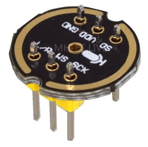
- a digital I2S microphone, like the INMP441 (datasheet)
Waag society uses the Invensense ICS4342 microphone in their kit 2.1. Myself, I ordered a couple of INMP441 microphones from Aliexpress.
The microphone is connected to the microcontroller as follows:
- INMP441 GND to ESP32 GND
- INMP441 VDD to ESP32 3.3V
- INMP441 SD to ESP32 A4/32
- INMP441 SCK to ESP32 A16/14
- INMP441 WS to ESP32 15
- INMP441 L/R to ESP32 GND
The connection carries only digital signals (max 3 MHz or so). No sensitive analog electronics are needed, the microphone and the microcontroller are simply connected using "dupont" wire.
The clock signal is 64 times higher than the sample clock, so at a sample rate of 44100 Hz, this means 2.8 MHz. This might be a bit high for a random wire, probably we should keep this connection short.
Software
Initial code can be found on github.
What the software should do:
- Take an audio measurement from the microphone at a regular interval (say 1 second every 10 seconds)
- On the recorded audio, perform a 4096-point real->complex FFT with a windowing function (flat-top for example).
- Calculate power for each FFT-bin (Im-squared + Re-squared) and sum up bins per octave.
- Calculate statistics, e.g. minimum/average/maximum over a 5 minute interval and convert to a logarithmic scale (decibels)
- Every 5 minutes, send the statistics to the network using WiFi or LoRa
The network receives the raw decibel values and can apply corrections for specific microphones, do A-weighting, etc.
To investigate:
- https://github.com/maspetsberger/esp32-i2s-mems
- TODO library that performs FFT on ESP32