SpaceBlaster: Difference between revisions
m add future plans |
|||
| (35 intermediate revisions by 4 users not shown) | |||
| Line 3: | Line 3: | ||
|Picture=SpaceBlaster.jpg | |Picture=SpaceBlaster.jpg | ||
|Omschrijving=Speaker soundsystem | |Omschrijving=Speaker soundsystem | ||
|Status= | |Status=In progress | ||
|Contact=Jelly | |Contact=Jelly | ||
}} | }} | ||
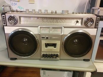
The SpaceBlaster is the ideal hackerspace portable speaker soundsystem. It's the competitor of the [[DeBASS]] and the DeCRASH. | The SpaceBlaster is the ideal hackerspace portable speaker soundsystem. It's the competitor of the [[DeBASS]] and the [[DeCRASH]]. | ||
== Materials == | == Materials == | ||
* 2*50 W digital amplifier board TPA3116D2 (two-channel) | * 2*50 W digital amplifier board TPA3116D2 (two-channel) | ||
* | * [https://getchip.com/ C.H.I.P.] | ||
* Arduino nano | |||
* 7V-24V To 5V 3A Power Module DC-DC 5V USB Output | |||
== | == Buttons == | ||
One tri-state switch has been connected, I will use two GPIO pins to detect in which state the switch is to save GPIO pins. | * 6 normal buttons (retain state when pressed) | ||
* 1 power button | |||
* 6 potentiometers (One used to control the volume and connected to the amplifier, other one is used for changing the FM band) | |||
* 5 tri-state switch (one tri-state switch requires three gpio pins) | |||
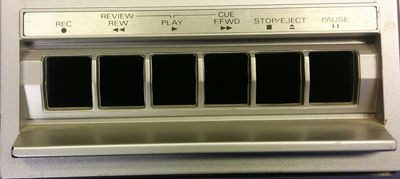
* 6 Cassette recorder buttons | |||
== Possible button functions == | |||
* WiFi on/off | |||
* Bluetooth on/off | |||
* Audio filters using a tri-state switch: disabled, echo, hall, room. | |||
* Potentiometer of FM band => playlists / radio streams. | |||
* USB to serial from chip for debugging access. | |||
* Treble & Bass potentiometer | |||
== Cassette record buttons == | |||
[[Image:spaceblaster_casette_recorder.jpg|400px]] | |||
== Progress == | |||
=== 23-12-2016 === | |||
Equalizer support using ALSA: | |||
apt install libasound2-plugin-equal | |||
And configuring an asound.conf using the following link. https://wiki.archlinux.org/index.php/Advanced_Linux_Sound_Architecture#System-wide_equalizer | |||
=== 27-11-2016 === | |||
Installed one SN74HC165N shift register to be able to hook up most of the buttons :). | |||
See the following ASCII diagram for the shift register pin and function. | |||
+ + + + + + + + + | |||
| | | | | | | | | | |||
+-+-+ +-+-+ +-+-+ +-+-+ +-+-+ +-+-+ +-+-+ +-+-+ +-+-+ | |||
| | | | | | | | | | | | | | | | | | | |||
| | | | | | |Pot| |Pot| |Pot| |Pot| | | |Two| | |||
| | | | | | | | | | | | | | | | |St.| | |||
+---+ +---+ +---+ +---+ +---+ +---+ +---+ +---+ +---+ | |||
Front HIGH Pin 7 HIGH HIGH | |||
Middle Pin 4 Pin 6 PIN 1 Pin 3 | |||
Back Pin 5 HIGH PIN 2 | |||
I've cleared a lot of the second PCB, removed resistors, caps etc. Removed overall loose wiring. | |||
Created a custom JHT connector for the C.H.I.P.'s UART pins, the outside of the radio will have an usb | |||
plug (mini, micro?) so I can debug the C.H.I.P. without opening the case! | |||
=== 26-11-2016 === | |||
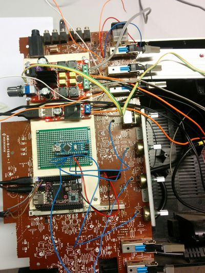
Amplifier, 7-40V DC DC to USB converter and arduino board have been screwed down | |||
on top of the old PCB. Speakers cable have been hooked up and a power brick has been installed | |||
with a new schuko (c13) plug in the side of the radio. | |||
[[Image:spaceblaster_board_layout.jpg|400px]] | |||
=== 22-11-2016 === | |||
Potentiometers are hooked up to the Arduino, three buttons have been soldered. | |||
=== 20-11-2016 === | |||
Stripped the main board of all transistors and other electronic components except the switches and potentiometers. | |||
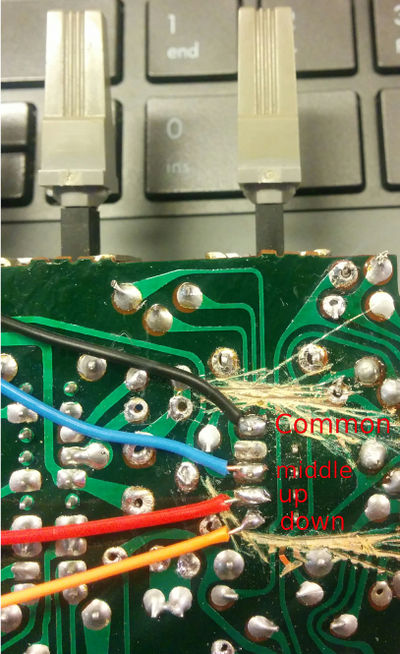
One tri-state switch has been connected, I will use two GPIO pins to detect in which state the switch (up, middle, down) is to save GPIO pins. | |||
[[Image:SpaceBlaster_sp3t.jpg|400px]] | [[Image:SpaceBlaster_sp3t.jpg|400px]] | ||
| Line 32: | Line 98: | ||
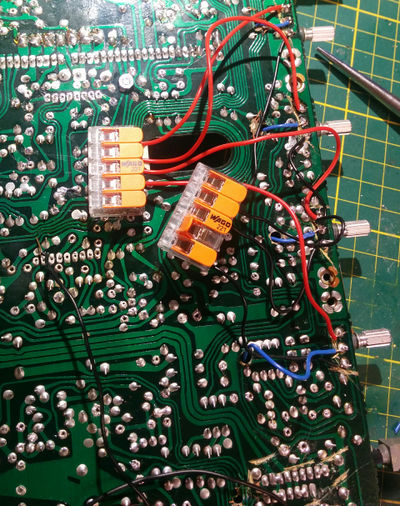
[[Image:Spaceblaster_wagos_ftw.jpg|400px]] | [[Image:Spaceblaster_wagos_ftw.jpg|400px]] | ||
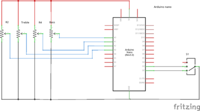
Arduino nano will be used for digital gpio and analog input, data send over serial to the ARM board. Which will in software control bass, treble, switches for pause, play, stop. | |||
[[Image:Spaceblaster_scheme.png|400px]] | |||
== Treble, Bass mixing in software == | |||
Pulseaudio with LADSPA plugin? http://plugin.org.uk/ http://plugin.org.uk/ladspa-swh/docs/ladspa-swh.html | |||
== future plans == | == future plans == | ||
* Battery powered / charging integrated | * Battery powered / charging integrated | ||
* Jack in for phones | |||
* Jack in for phones | * bluetooth audio | ||
* display now playing track | |||
* USB connector (outside) to C.H.I.P. UART | |||
* New speakers | |||
* | |||
Latest revision as of 22:10, 23 December 2016
| Project SpaceBlaster | |
|---|---|
| |
| Speaker soundsystem | |
| Status | In progress |
| Contact | Jelly |
| Last Update | 2016-12-23 |
The SpaceBlaster is the ideal hackerspace portable speaker soundsystem. It's the competitor of the DeBASS and the DeCRASH.
Materials
- 2*50 W digital amplifier board TPA3116D2 (two-channel)
- C.H.I.P.
- Arduino nano
- 7V-24V To 5V 3A Power Module DC-DC 5V USB Output
Buttons
- 6 normal buttons (retain state when pressed)
- 1 power button
- 6 potentiometers (One used to control the volume and connected to the amplifier, other one is used for changing the FM band)
- 5 tri-state switch (one tri-state switch requires three gpio pins)
- 6 Cassette recorder buttons
Possible button functions
- WiFi on/off
- Bluetooth on/off
- Audio filters using a tri-state switch: disabled, echo, hall, room.
- Potentiometer of FM band => playlists / radio streams.
- USB to serial from chip for debugging access.
- Treble & Bass potentiometer
Cassette record buttons
Progress
23-12-2016
Equalizer support using ALSA:
apt install libasound2-plugin-equal
And configuring an asound.conf using the following link. https://wiki.archlinux.org/index.php/Advanced_Linux_Sound_Architecture#System-wide_equalizer
27-11-2016
Installed one SN74HC165N shift register to be able to hook up most of the buttons :). See the following ASCII diagram for the shift register pin and function.
                 +       +       +       +      +      +      +      +      +
                 |       |       |       |      |      |      |      |      |
               +-+-+   +-+-+   +-+-+   +-+-+  +-+-+  +-+-+  +-+-+  +-+-+  +-+-+
               |   |   |   |   |   |   |   |  |   |  |   |  |   |  |   |  |   |
               |   |   |   |   |   |   |Pot|  |Pot|  |Pot|  |Pot|  |   |  |Two|
               |   |   |   |   |   |   |   |  |   |  |   |  |   |  |   |  |St.|
               +---+   +---+   +---+   +---+  +---+  +---+  +---+  +---+  +---+
    Front      HIGH           Pin 7                                HIGH    HIGH
    Middle     Pin 4          Pin 6                                PIN 1   Pin 3
    Back       Pin 5          HIGH                                 PIN 2
I've cleared a lot of the second PCB, removed resistors, caps etc. Removed overall loose wiring. Created a custom JHT connector for the C.H.I.P.'s UART pins, the outside of the radio will have an usb plug (mini, micro?) so I can debug the C.H.I.P. without opening the case!
26-11-2016
Amplifier, 7-40V DC DC to USB converter and arduino board have been screwed down on top of the old PCB. Speakers cable have been hooked up and a power brick has been installed with a new schuko (c13) plug in the side of the radio.
22-11-2016
Potentiometers are hooked up to the Arduino, three buttons have been soldered.
20-11-2016
Stripped the main board of all transistors and other electronic components except the switches and potentiometers.
One tri-state switch has been connected, I will use two GPIO pins to detect in which state the switch (up, middle, down) is to save GPIO pins.
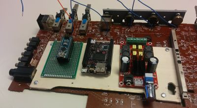
Possible layout of the ARM board, arduino and amplifier.
Wago's are used on the other side for the ground / power to avoid cable clutter mess :)
Cable mgmt:
- Blue cable => potentiometer
- Black => Ground
- Red => 5V
Arduino nano will be used for digital gpio and analog input, data send over serial to the ARM board. Which will in software control bass, treble, switches for pause, play, stop.
Treble, Bass mixing in software
Pulseaudio with LADSPA plugin? http://plugin.org.uk/ http://plugin.org.uk/ladspa-swh/docs/ladspa-swh.html
future plans
- Battery powered / charging integrated
- Jack in for phones
- bluetooth audio
- display now playing track
- USB connector (outside) to C.H.I.P. UART
- New speakers
