GorbaDisplay: Difference between revisions
| Line 71: | Line 71: | ||
|2||GND||Ground | |2||GND||Ground | ||
|- | |- | ||
|3||?|| | |3||?||A3 of 74HCT541 | ||
|- | |- | ||
|4||?|| | |4||?||A0 of 74HCT541 | ||
|- | |- | ||
|5||COL_SEL1|| | |5||COL_SEL1||bit 1 of row multiplexer,A1 of 74HCT541 | ||
|- | |- | ||
|6||COL_SEL2|| | |6||COL_SEL2||bit 2 of row multiplexer,A0 of 74HCT541 | ||
|- | |- | ||
|7||?|| | |7||?|| | ||
|- | |- | ||
|8|| | |8||?|| | ||
|- | |- | ||
|9|| | |9||ROW_DATA|| | ||
|- | |- | ||
|10||COL_SEL0|| | |10||COL_SEL0||bit 0 of row multiplexer,A4 of 74HCT541 | ||
|- | |- | ||
|11||?|| | |11||?||A5 of 74HCT541 | ||
|- | |- | ||
|12||ROW_CLK||SRCK of column shift register | |12||ROW_CLK||SRCK of column shift register,A6 of 74HCT541 | ||
|- | |- | ||
|13||VCC||Power | |13||VCC||Power | ||
Revision as of 19:44, 4 August 2023
| Project GorbaDisplay | |
|---|---|

| |
| Public transport LED display | |
| Status | Initializing |
| Contact | bertrik, User:Eloy |
| Last Update | 2023-08-04 |
Introduction
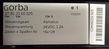
This project is about reverse engineering a former public transport LED display. It consists of Z panels of each X * 16 LEDs. Each panel has 16 amber LEDs vertically.
The plan is to make the display fully addressable as a bitmap display over a network connection, preferably with individually controllable brightness per pixel.
TODO:
- more reverse engineering by tracing out the connector to the individual lines of the integrated circuits
- is there a separate power supply line to the board? if so, can we power our new microcontroller from the 14-pin connector?
- measure clock frequencies (column clock, line update frequency) of original controller board
- write software to control this thing, e.g. for ESP8266
- investigate https://github.com/qisun1/ESP8266_LED_64x16_Matrix , seems to be a similar display
Hardware
This thing consists of two main parts:
- a control board, with logic to receive (for example) text messages over a serial connection and convert them to a bitmap display on the display board
- a display board, with logic to light up each LED, consisting of 4 panels of 16x16 LEDs each
Each panel has two 14-pin connectors, one incoming and one outgoing (to the next panel)
It has a light sensor to sense the ambient light level.
It is powered by 24V. Each panel contains an LM2678 chip, a.k.a. as the Texas instruments "simple switcher".
Each LED has a 10 ohm resistor in series. LEDs are amber/orange.
Theory of operation
My guess this is probably another row-multiplexed display. The display can light up one row at a time. By quickly lighting up each row in succession, the illusion to a human observer is that all LEDs are controlled simultaneously.
The display board contains the following integrated cicruits:
- 74HC541, an octal buffer/line driver, probably buffers all signals coming in from the 14-pin connector to the rest of the electronic on the display board
- 74HC238, a 3-to-8 line decoder/demultiplexer, probably selects which row is currently being lit up
- group of 4x IRF7425, power MOSFET, probably for driving a row of LEDs with
- a whole bunch of TPIC6C596, 8-bit shift register, probably drives the columns inside one row of LEDs
column multiplexer
The demultiplexer handles only 3 bits, enough for 8 rows. Perhaps there are two of them to handle 16 rows: one for the top 8 rows and one for the bottom 8 rows.
row registers
Each panel contains 32x16 pixels. It has a shift register of 4x32 pixels.
Possibly one out of four rows can be lit at a time this way.
The shift registers of one panel are wired up in series. At the end of the shift register chain of each panel, there is another 596 chip, the output feeds into the data pin of the output 14-pin connector.
14-pin connector
My guess for the pinout so far is:
| Pin | Id | Remark |
|---|---|---|
| 1 | GND | Ground |
| 2 | GND | Ground |
| 3 | ? | A3 of 74HCT541 |
| 4 | ? | A0 of 74HCT541 |
| 5 | COL_SEL1 | bit 1 of row multiplexer,A1 of 74HCT541 |
| 6 | COL_SEL2 | bit 2 of row multiplexer,A0 of 74HCT541 |
| 7 | ? | |
| 8 | ? | |
| 9 | ROW_DATA | |
| 10 | COL_SEL0 | bit 0 of row multiplexer,A4 of 74HCT541 |
| 11 | ? | A5 of 74HCT541 |
| 12 | ROW_CLK | SRCK of column shift register,A6 of 74HCT541 |
| 13 | VCC | Power |
| 14 | VCC | Power |
There are possibly pins for:
- row select, bit 0
- row select, bit 1
- row select, bit 2
- row select, bit 3
- row-enable
- shift register data
- shift-register clear
- shift-register data
- analog LDR value
- remote control input
- power pin
- ground pin
