User:Luteijn
Intro
Hoi, ik ben Pieter en ik ben relatief nieuw hier..
Ik heb eind vorige eeuw in Delft Elektrotechniek gestudeerd, en daarna als 'Netwerk Specialist' gewerkt aan een aantal internationale IP netwerken, en af en toe tussen de bedrijven door nog wel eens aan electronische projectjes geknutseld, die dan in min of meer affe toestand in een doos belandden. Tussendoor heb ik ook nog ergens tijd gevonden om een examen voor radiozendamateur te doen (PC1PCL).
Als de projectendoos en junk-box een beetje uitgezocht zijn, hoop ik me er toe te kunnen zetten wat met microcontrollers te gaan doen, bijvoorbeeld om een klein bakentje voor onder een vlieger of luchtballon of ergens in een bos als radiovos te klussen.
Project Status/Voortgang:
(deze lijst is zelf een Work In Progress)
Project "Zoek 't uit"
| Project Luteijn/ZoekZoek | |
|---|---|
| Status | In progress |
| Contact | Luteijn |
| Last Update | 2018-01-19 |
WIP:
- De grote doos met projecten en onderdelen in de kast grotendeels uitgezocht, moet nu nog wel een schifting in "korte termijn", "lange termijn" en "moet weg" komen, en dan alleen de korte termijn meuk op de space laten staan. De twee kleinere doosjes moeten nog wat verder uitgezocht worden, idee is om daar uiteindelijk maximaal 2 projecten die "onder handen" zijn in te stallen. De twee platte vakjesdozen met losse componenten moeten ook nog opgeschoond zodat er geen overlap/doublure is met voorraad revspace (dus alleen bijzondere componenten uit eigen doos, bijv. bijzonder duur, bijzonder zeldzaam of alleen bijzondere mensen zouden er iets in zien dit op voorraad te houden ;) )
Project "Projecten Laptop":
| Project Luteijn/Laptop | |
|---|---|
| Status | In progress |
| Contact | Luteijn |
| Last Update | 2018-01-19 |
DONE:
- Compaq/HP 6730b aangeschaft op computeroutlet
- Debian testing erop gezet
- Oude extra batterij eraan gehangen
- HD vervangen door SSD en Debian Jessie erop
TODO:
- 2x rubbertjes voor achterste voetjes opzoeken
- apt-get update && apt-get upgrade regelmatig uitvoeren
- meer software installeren wanneer er iets blijkt te missen
- vim environment om arduino's te programmeren opzetten
Project "Microcontrolled radio beacons":
| Project Luteijn/Beacon | |
|---|---|
| Status | In progress |
| Contact | Luteijn |
| Last Update | 2018-01-19 |
DONE:
- Arduino en arduino clones devboardjes programmeren werkend met laptop via arduino ide.
- 1 Arduino clone aangepast (condensator tussen reset en gnd, programmer sketch erop, kabeltjes naar breadboard) om als programmer te werken voor attiny en losse atmega chips.
- standalone ATTINY45 op 5V met de 'blink sketch' geflashd via de clone programmer
- morsebaken sketch verder uitgewerkt en op de ATT45 gezet. LEDje knippert nu morseseinen
- ATTINY 45 op 3.3 V laten lopen zodat interface met HOPERF radiotjes geen gedoe geeft. (3V lithium knoopcel)
- ATTINY 45 getest met HOPERF radiotje in CW mode. Werkt verbazend goed met prima ontvangst door de hele gang van het gebouw tot op het parkeerterrein met het bakentje op een breadboardje in de klusbunker
- vossejachtbakentje gemaakt in een verrassingsei. Zie RadioEi.
- programmer standalone (losse ATMEGA) en robuuster (doosje) maken zodat dev-bordje weer vrij komt --> USBasp.
- Vervolg RadioEi: ATTINY en/of ATMEGA op 3.3 V interfacen met HOPERF radiotje zodat andere frequencies en modes (e.g. rtty) gebruikt kunnen worden en hier mee testen: eerste tests zijn wat teleurstellend, minimale shift in FSK mode is erg groot, resolutie van de 'werk-frequentie' lijkt ook erg grof te zijn. Moet wel mogelijk zijn om een aantal zendertjes elk op een eigen frequentie in OOK-modus te laten werken.
- Onderzoeken werkbaarheid seriele interface op ATT45/ATT85 -> softserial werkt, maar kost vrij veel geheugen. Debug strings kort houden of met progmem werken, anders loop je zo uit het werkgeheugen.
TODO:
- Vervolg RadioEi: verder testen met mogelijkheden HOPERF zendertje.
- als reference design Meurs Mk2 nabouwen op breadboard? kickstarter pagina code op github
- GPS, radio, uController samenvoegen en aan baken software klussen om een pico baken te maken.
Project "Microcontrolled relay board":
| Project Luteijn/Relay | |
|---|---|
| Status | In progress |
| Contact | Luteijn |
| Last Update | 2018-01-19 |
My garage-door-opener can be controlled by pulling a particular DC 20V pin on the controller down. This is meant for a (key) switch to control operate the door or turn on the LED lamp. I've wired the pin through two relays. One pulls the pin low enough (using a 100 Ohm resistor to form a voltage divider with a pull-up inside the controller) to activate the lamp, the other shorts it to ground, which will activate the door actuator. The control is rather crude, basically a pulse will stop a moving door, or starts a non-moving door. Direction is reversed from whatever was the last direction., although this is not 100% guaranteed it seems. Normally not an issue as you'd see the direction of the door and can just operate the switch to compensate. Of course, the idea is that the relays can be operated from anywhere, to let people in when unable to open a door by hand. So it's useful to be able to 'see' if the door is open or closed. This is sensed via a reed relay and a magnet stuck to the door. if the door opens, the magnet travels away from the reed relay, changing the voltage over it, which is measurable by the relay-controller.
Typical Relay Board schematic: http://howtomechatronics.com/wp-content/uploads/2015/09/Relay-Module-Circuit-Schematics.png
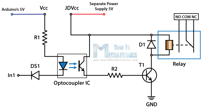
I don't provide Vcc to the optocoupler, but use an 'enable' pin. Also, the idea is to not have a common ground. The relay board and a separate powersupply is of course way more expensive than the bare ATT45 I ended up using instead of an arduino, so if the relay borks and puts 30 VDC (or mains, if you're switching that) on the low voltage side, then it wouldn't matter too much that the Tiny is also fried. Still, especially during prototyping I'd rather keep things optically isolated. Now that it works, and I know the relay doesn't overload the Vcc, I've cheated and use one supply for both relay board and the Tiny.
The relay-controller runs on an ATT45, which talks over (software) serial to a host computer (GLInet router in my case) and from there to the rest of the world. Access control is handled on the host computer, for flexibility and to save space on the ATT45. All output is also rather terse to save space on the ATT45. For the same reason, the code has its static strings broken up into smaller units and I use #defines instead of 'const' variables.
As I was short on pins, I'm using the active low reset pin as an analogue input, making sure not to drop it too low to reset the Tiny. I found I needed a rather big Capacitor to decouple the reset line. Otherwise when one of the relays switched on, the Tiny would reset due to what I suspect was (E)MI. It might have also helped not to run the switched 30V right next to the long leads connecting the reed relay to the reset pin...
The reed contact that senses door state is normally kept closed by a small magnet. It connects the reset pin to ground via a pulldown resistor, there is also a pullup resistor, forming a voltage divider. Dimensioned so that Voltage goes from Vcc (5v from USB-serial dongle) when the reed switch (and the door) is open so just the pull-up is connected to about 4.2 volt when it is closed. Unfortunately it is a bit tricky to use a bias magnet to get the switch to be (reliably) open when the door is closed (and closed when it is not). So there's always some current flowing here, but as the total R the Vcc is over is about 50kΩ, we're talking about 100μA, which I think we can afford, even if the thing would be battery powered, as the tiny is using 10 (50) times that running at 1 (8) MHz. Probably could use even higher value resistors if needed to drop the sense current further.
/* relay-controller-tiny.ino */

#include <SoftwareSerial.h> // There is no uart on the ATTiny

#define versionstring "TRC1" // Tiny Relay Controller 1.

#define ledPin (0)    // pull low to close the relay controlling the LED lamp
#define doorPin (1)   // pull low to close the relay controlling the door
#define enablePin (2) // High to enable, Low to disable the optocouplers
#define RX (3)  // serial link to host
#define TX (4)  // serial link to host
#define sensorPin (A0) // on reset!
#define rate (19200) // 9600 might be better.

#define crnl "\r\n" // help compiler optimize

bool ansi=false; // there's a bit of color use possible
bool enabled=false; // keeps track of the enable pin being high or low

unsigned char cutoff=244; //cutoff value between open and closed sensor, can be tweaked during runtime
bool sensor=false;  // door open or closed
bool prevsensor=false  // used to detect state changes.

signed char timeout=100;  // watchdog timeout value. note signed char so 127 is max
signed char timer=timeout; // current timer value, if it goes under 0, 'disable' optocouplers.


SoftwareSerial Serial(RX,TX); // control connection to host.

void setup() {
  pinMode(enablePin,OUTPUT);
  digitalWrite(enablePin, LOW); // make sure optocouplers are/stay disabled asap.
  pinMode(doorPin,OUTPUT);
  digitalWrite(doorPin, HIGH); // active low, so enable current can be sunk, to light the led inside opto
  pinMode(ledPin, OUTPUT);
  digitalWrite(ledPin, HIGH); // active low, so enable current can be sunk, to light the led inside opto
  pinMode(sensorPin, INPUT); //will be using this as an analogue input so it can share the reset pin

  enabled=false; // initially we will not be in enable mode
  Serial.begin(rate); //start serial link
  delay(10);
  myversion(); // hello world!
  sensor=(analogRead(sensorPin)/4); // initialize door sensor value
  prompt(); // ready for input
}

void prompt() {
  normal(); // color off
  line(); // new line
  sensor?bred():bblue(); // color bold red when door open, blue when closed
  Serial.write(sensor?"O":"C"); // show O for open, C for closed
  enabled?byellow():bgreen(); // bold yellow when enabled, green when not
  Serial.write(enabled?"# ":"> "); // cisco style prompt to show enabled/disabled
  normal(); // normal color
}

void myversion(){ // simply writes version string to serial line, useful when reconnecting tty
 line();
 Serial.write(versionstring);
}

void pulse(int what,int time){ // pulse a pin for some ms
  digitalWrite(what,LOW);
  delay(time);
  digitalWrite(what,HIGH);
  return;
}
void disable() { // pull enable pin down to de-arm the optocouplers
  if (enabled) { // we call this every time the watchdog times out, just to be sure, but no need to do feedback when not enabled anyway
    line();
    Serial.write("D");
  }
  digitalWrite(enablePin,LOW); // always call, just to be on the safe side.
  if (enabled) {
    Serial.write("!");
  }
  enabled=false;
}

void enable() { // arms the torpedoes, eh optocouplers by supplying a Vcc
  enabled=true;
  line();
  Serial.write("E");
  digitalWrite(enablePin,HIGH);
  Serial.write("!");
}

void line(){ // newline. might help to make this an inline function or macro instead.
  Serial.write(crnl);
}
// below are some functions to help print out ansi control sequences
void aesc(){ //<esc>[9 leads in all the color sequences
    Serial.write(27);
    Serial.write("[9");
}
void bblack(){
    if (!ansi) return;
    aesc();
    Serial.write("0m");
}
void bred(){
    if (!ansi) return;
    aesc();
    Serial.write("1m");
}
void bgreen(){
    if (!ansi) return;
    aesc();
    Serial.write("2m");
}
void byellow(){
    if (!ansi) return;
    aesc();
    Serial.write("3m");
}
void bblue(){
    if (!ansi) return;
    aesc();
    Serial.write("4m");
}
void bmagenta(){
    if (!ansi) return;
    aesc();
    Serial.write("5m");
}
void bcyan(){
    if (!ansi) return;
    aesc();
    Serial.write("6m");
}
void normal(){
    if (!ansi) return;
    aesc();
    Serial.write(";0m"); // needs the ; so the 9 is not directly prepended
}


void loop() {
    // put your main code here, to run repeatedly:
  char c;
  if (Serial.available()){  // get a character from input if available
    timer=timeout;
    c=Serial.read();
  } else {
    c=' '; // nop command.
  }


  switch (c) { // command dispatcher
    case 'a': //toggle ansi colors
    ansi=ansi?0:1;
    break;
    case 's': //dump current sensor value
    case '=':
      line();
      Serial.write("=");
      Serial.print((analogRead(sensorPin)/4));
      Serial.write("!");
    break;
    case '-': // these adjust the cutoff value to distinguish between open and closed door
    if (enabled) { // need to enable to mess with cutoff values
      cutoff-=2;
    } //fall through, increase by one again, then print new value
    case '+': //increase cutoff (if enabled)
    if (enabled) {
      cutoff++;
      } // fall through, print new value
    case 'c': // dump current cutoff value
    line();
    Serial.write("C");
    Serial.print(cutoff);
    Serial.write("!");
    break;
    case 'd': // disable
    disable();
    break;
    case 'o': // operate door
    Serial.write(crnl);
    Serial.write("O");
    pulse(doorPin,1000); // 1 sec is more than enough, might lower this to save energy ;)
    Serial.write("!");
    break;
    case 'e': // enable - could add a small state machine to read in a kind of secret
    enable(); // but we just trust the upstream access control
    break;
    case 'l': // operates the relay for the led lamp.
    Serial.write(crnl);
    Serial.write("L");
    pulse(ledPin,1000);
    Serial.write("!");
    break;
    case 'v': // print version string again
    myversion();
    break;
    case ' ': // NOP
    // do not do anything if no command received
    break;
    default: // debug by echoing unknown command back; no 'help' screen as takes too much space
    line();
    Serial.write(c);
    Serial.write("?");
    break;
  }

  prevsensor=sensor; // save old sensor value
  sensor=(cutoff<(analogRead(sensorPin)/4)); // closed door, closed reed, pulls down.
  if (sensor!=prevsensor) { // door state changed?
    prompt(); // print a prompt, which will show the changed state
  }

  if (--timer<0) { // decrease watchdog timer
    timer=timeout; // reset  timer
    if (enabled!=0) { // if disabled already then don't spam prompts
      c='~'; //will trigger prompt to show soon to be disabled mode
    }
    disable(); // always call disable, just in case pin glitched on
  } else {
    delay(100); // 100 ms reaction time is fine, timeout=100 units of 100ms this way
  }

  if (c!=' ') { // prompt for new command
    prompt();
  }
}
DONE:
- control typical 'arduino' 2-relay board with NodeMCU.
- control typical 'arduino' 2-relay board with ATTiny 45.
- garage-door opener controller for NodeMCU as PoC - web frontend.
- garage-door opener controller for ATT45, serial 'front'end.
- made a box for mains->USB power brick to connect as separate power supply for coils, but since the TCO of just using the ATT and/or USB-serial converter as the 'fuse' compared to running another powerbrick seems lower, just connected the relay Vcc to the same Vcc from the USB-serial converter. NOTE: the enable pin feeds optocouplers, so the 'jumper' is open.
TODO:
- invert logic on door open detection reed contact so open circuit when door closed?
- add more reed contacts at different voltages to detect e.g. fully opened door, or checkpoints along the way. maybe some kind of ultrasound distance meter to detect how far the door is opened?
Project "Microcontrolled MIDI units":
| Project Luteijn/MIDI | |
|---|---|
| Status | In progress |
| Contact | Luteijn |
| Last Update | 2018-01-19 |
DONE:
- Tests/POC programs to control stuff on laptop (alsa volume, PulseAudio volume, X mouse cursor, even text input) with MIDI keyboard and 'DJ' controller connected via usb.
- Successful POC testing based on [RadioEi] code adjusted to sending midi events instead, controlled with analogue inputs (potentiometers)
- POC testing midi receiver, failed as optocoupler used too slow, better suited as PTT switcher, which is where I originall got those for.
- Ordered 100 units of 6N137 DIP8 from Ali - arrived 2016-01-12
TODO:
- Test with new Optocouplers to make a working receiver, maybe use demux chips and the slow optocouplers (or just the fast ones as I have plenty now) to control stuff (eg. radio equipment? ) via midi.
- Build several controllers (Buttons, knobs etc.)
- look into MIDI over USB more, as a lot of interesting ready made controller units work with USB not the DIN plugs. At the very least would be cool to make a converter box.
- might just need to be cost-efficient and do it this way, using a cheap midi-usb converter and gut that.
Project "HAB":
| Project Luteijn/HAB | |
|---|---|
| Status | In progress |
| Contact | Luteijn |
| Last Update | 2018-01-19 |
DONE:
- POC parachute van oude paraplu
- POC RTTY zenden via NTX radio met arduino dev board
- POC CW zenden via HOPERF radio met arduino dev board
- POC GSM module uitlezen met arduino dev board
TODO:
- radiobaken klussen ("Microcontrolled radio beacons" project) (evt kan het RadioEi hier al voor gebruikt worden, maar dan moet er dmv kruispeilingen etc. bepaald worden waar de ballon is, omdat het Ei nog niet slimgenoeg is om zelf aan plaatsbepaling te doen.)
- Ballon sourcen
- Gas regelen (zelf H2 maken via elektrolyse op zonne-energie ("Build your own Bomb" project), of toch maar He kopen)
- Toestemming etc. regelen voor loslaten.
- Ballon oplaten
- Samenwerken met anderen om dit makkelijker en leuker te maken?
Project "Velddag Radio":
| Project Luteijn/FieldDay | |
|---|---|
| Status | Initializing |
| Contact | Luteijn |
| Last Update | 2018-01-19 |
DONE:
- Parkeerterrein gescout.
TODO:
- Andere radio enthousiatelingen mee-activeren e.g. Maxell Bertrik Sikken Crashjuh etc.
- top-end-fed antenne inelkaar zetten
- POC: /A station uitproberen op 0.7-2-6-10-15-20-30-40-80-160 meter
- Activiteiten-scope bepalen en voorbereiden (antennes, opstel-plaatsen bezoekers, barbeknoeis etc.)
- Datum prikken voor de velddag en publiciteit spammen o.a. bij de Veron
Project "Miss Selenius":
| Project Luteijn/Misc | |
|---|---|
| Status | In progress |
| Contact | Luteijn |
| Last Update | 2018-01-19 |
DONE:
- Zondag 2015-01-04: kitje van aliexpress inelkaar gesoldeerd om componenten te indentificeren. Tevens dino's inelkaar helpen plakken voor de kinderen.
- Zondag 2015-01-18: klok ledbanner gelijk gezet, met kind Izaak lange tekening gemaakt en geflipperkast.
- deze lijst niet bijgehouden
- computervoeding->labvoeding klussen -> Bouwpakketje?
TODO:
- deze lijst wel bij houden.
- een nette frontplaat 'accu-voeding' lasercutten ter vervanging van gefiguurzaagde geval dat nu dienst doet.
- 'accu-voeding' verbeteren, b.v. in een plastic bak zetten en meer idioten-bestendig maken.
- nog een computervoeding->labvoeding klussen -> Bouwpakketje?