Canadian NABU retro computer conversion to VGA out and 220V 50Hz
| Project NABU conversion | |
|---|---|
| |
| conversion to Euro version of the NABU PC | |
| Status | Initializing |
| Contact | Mahjongg |
| Last Update | 2023-03-28 |
The NABU Network (Natural Access to Bi-directional Utilities) was an early (1983) home computer system which was linked to a precursor of the World Wide Web, operating over cable TV. It operated from 1982 to 1985, primarily in Ottawa, Canada. Its functionality was then revolutionary, though it was not a commercial success. It has been called "The Internet — 10 years ahead of its time" (even though elements of the history of the internet predate it).
early 2023 an entrepreneur which had bought a stock of one thousand NABU systems after the company had gone bankrupt decided to try to sell this stock, which he had kept for 38 years. And as RETRO collectors discovered this fact, in the US a community quickly establishes itself after a well known retro computer fan and YouTuber Adrian's Digital Basement reported about it https://www.youtube.com/watch?v=HLYjZoShjy0 . another YouTube DJ Sures quickly decided to help to get the NABU functioning again without the Canadian Cable system, his YouTube channel can be found here: https://www.youtube.com/playlist?list=PLNT_tjSHIQ3lGJR_zOqh9gGeHzykR0spq but there are now many people helping out, and re-building their own NABU systems.
This development peaked my interest, and I decided to buy a NABU and accompanying cable set before they were all gone. As I don't have a credit card, or any other means to pay for one, I decided to ask my friends of the national computer games museum in Zoetermeer for help. And immediately one of the technical people (Frans Egmond) reacted to offer his help, and when he discovered what I tried to buy he was hooked too, and wanted one as well. he also told the owner of the museum (Hassan Tasdemir) about the NABU, and he wanted one for the museum. So now there are three NABU owners in the Netherlands, (all NABU buyers are registered in a database) and all of them are from this computer games museum.
The problem in getting a NABU to work in the Netherlands
The NABU is a Canadian system, and that means it is powered with 110 Volt 60 Hz, and has an NTSC composite video output, and neither of these two facts is ideal in the Europe of 2023. So Frans and me decided we would need to adapt the NABU for it to work, firstly we wanted to replace the NABU's power supply and FAN with a 220V 50Hz compatible equivalent.
The NUBU is a Z80 based system that uses a TMS9918A for video, and a AY-3-8910 PSG for sound, and so it has lots of similarities with the MSX computer standard, and several other early home computers and consoles.
The fact the it uses a TMS9918A for the VDP means that just as MSX it can be converted to PAL (and RGB output) by replacing the TMS9918A with a TMS9929A that generated PAL and could also support RGB by using its Y, R-Y and B-Y luminance and colour difference signals to convert to RGB signals.
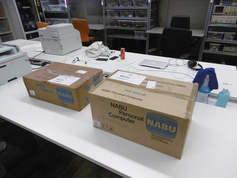
The NABU is in!
Left the network adapter (project box) right the NABU PC
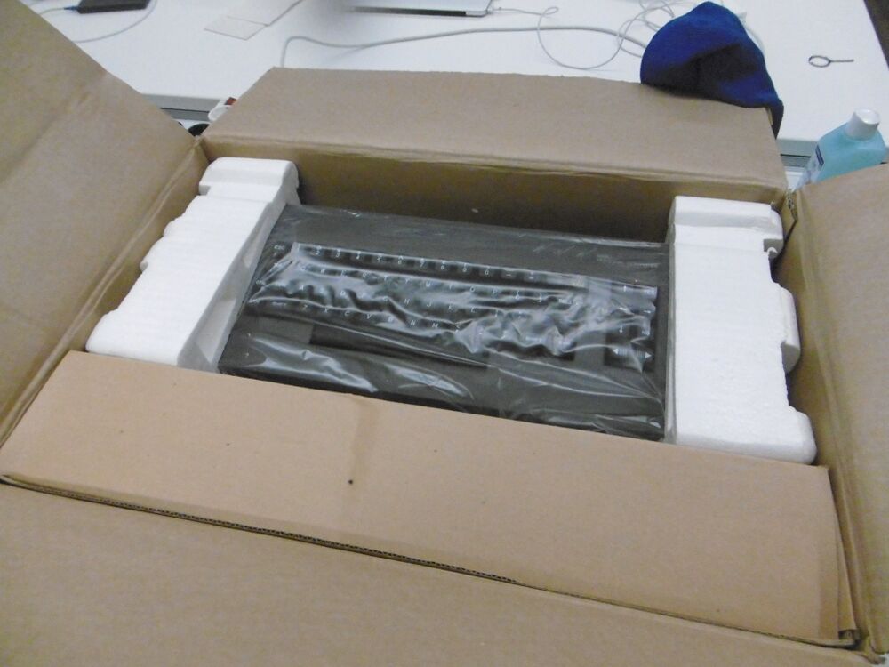
when you open the box at first you see the keyboard.
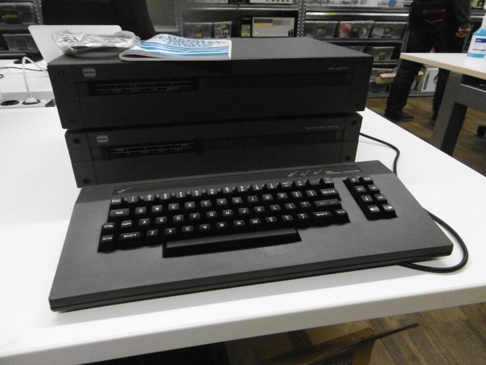
So this is how the complete system looks, with the PC below with the network adapter on top, and the keyboard in front. The keyboard has a VERY long cable, multiple meters long.
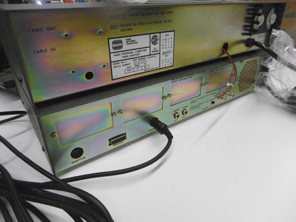
This is the backside, network adapter on top, PC below.
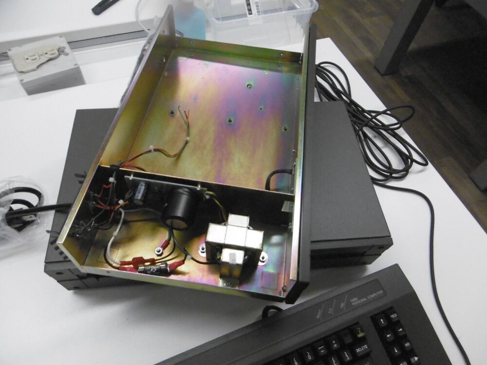
The network adapter is called a project box by the reseller, and the reason is the the box is completely empty, except for a simple linear regulator, and a few LED's.
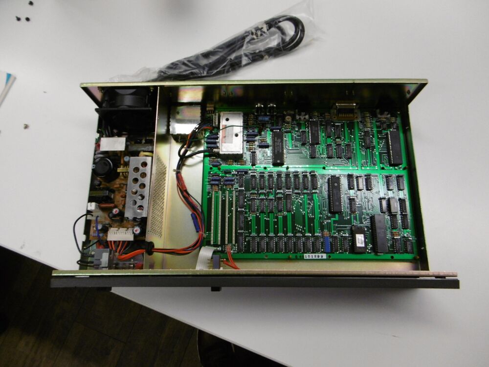
Instead the NABU PC is hardly empty! Left the switching power Supply and FAN, and right the mother board. The power supply is of the switching type, and measures 10cm wide, and 15cm deep. the FAN has screw-holes 72mm apart, and is 4cm thick there is 8,8cm height inside.
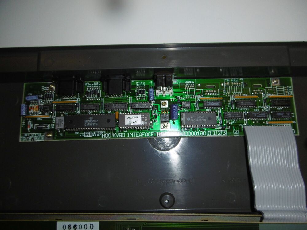
The keyboard contains an MC6803 CPU which has built in RAM and a small EPROM, but there is also an ADC0809CCN 8-bit A/D converter, probably to support paddles (analog joysticks).
Overview of NABU motherboard
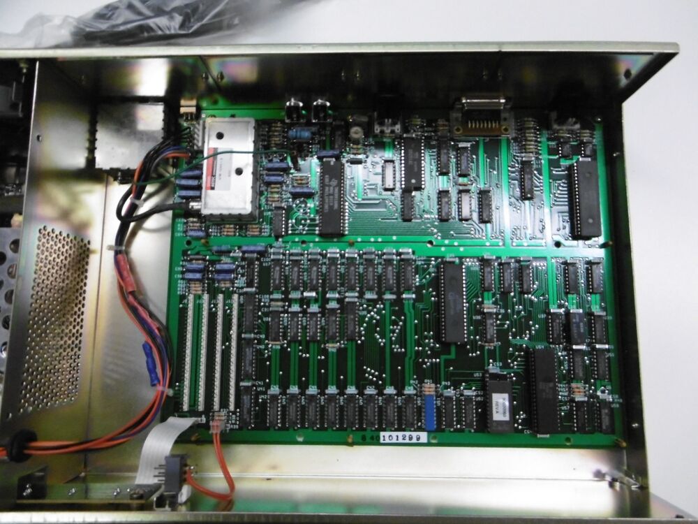
This is a flyover picture of the NABU's main PCB.
top left, the square metal box is the RF switch box, we won't be using anymore, and to the right of it is the RF modulator, we will not need as the NABU also has a composite video output.
Currently it outputs NTSC, (from a RCA connector, the other RCA plus outputs mono audio) but we will change that to PAL, and later also to component video (with a converter box we can convert this to RGB and to VGA.
Details
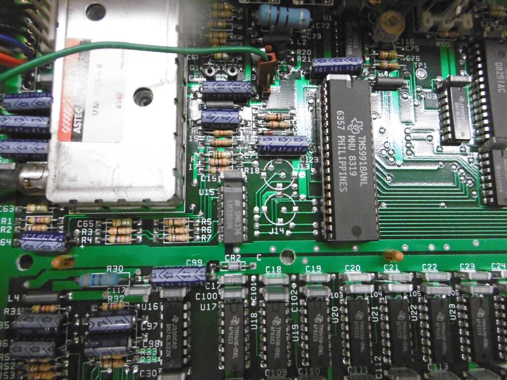
The top left quart of the PCB is dedicated to the video chip, the TMS9918A NL. The green wire running horizontal over the top controls the RF switch.
Below it is 16K, made from 16K x 1 DRAM chips type TMS4116. This is the video RAM that the TMS9918A NL uses, it is not part of the Z80 memory map but a dedicated 16K only for the video generation. It was first used in the Texas Instruments TI99/4 home computer, but there this ram was used as a complement for the very tiny 16-bit main RAM, on the NABU the Z80 has its own 64K byte of RAM.
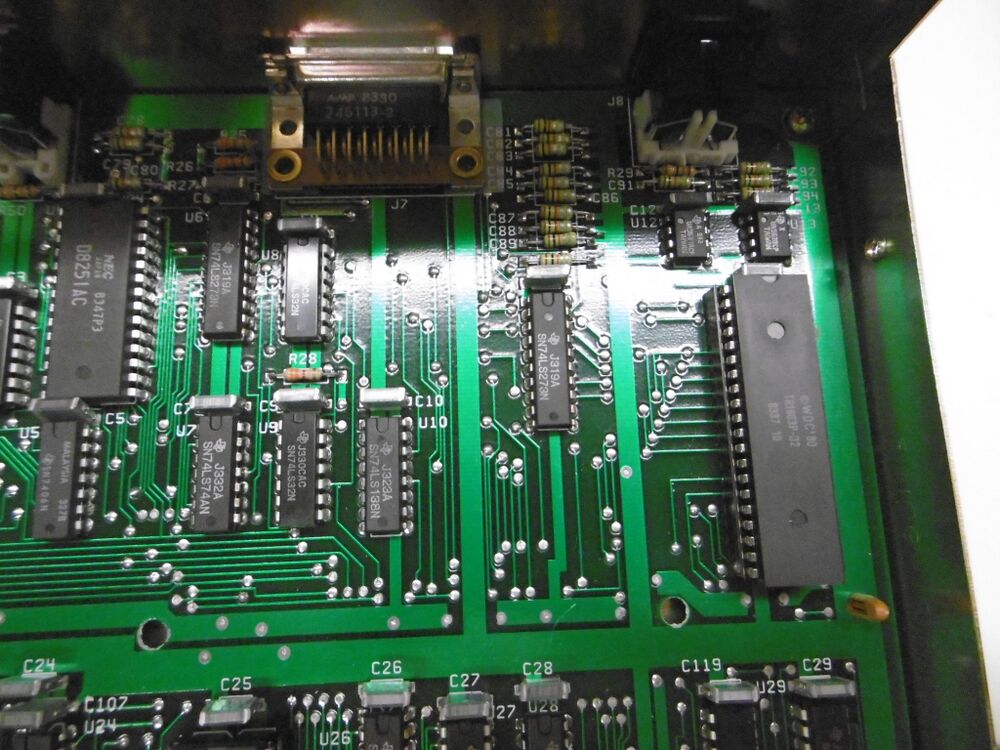
To the right (the top right quart) are chips dedicated to various serial interfaces, and a parallel printer interface (DB-15).
The D8251 is a Programmable Communications Interface made by iNTEL (and AMD) it is a somewhat simpler UART than the more commonly used 16550 UART found in PC's, that had build in cache. The 8251 is commonly used for modems, but in this case it communicates with the keyboard using the 6-pin DIN connector to the top left of it, it doesn't use RS232 levels but just 5V TTL levels. Not a serial interface but the Centronics connector top middle is used for a printer interface, and is a parallel port.
The large chip to the right is the Western Digital WDC TR1863 Universal Asynchronous Receiver/Transmitter, a high speed serial interface capable of very high speeds over a RS422 connection, used to the communication with the cable modem. It uses a 5-pin DIN connector, two balanced pairs, no GND connection is used so just 4-pins are used of the DIN. On the new old stock NABU's we use a USB to RS422 interface, and some software on a laptop to emulate the cable modem.
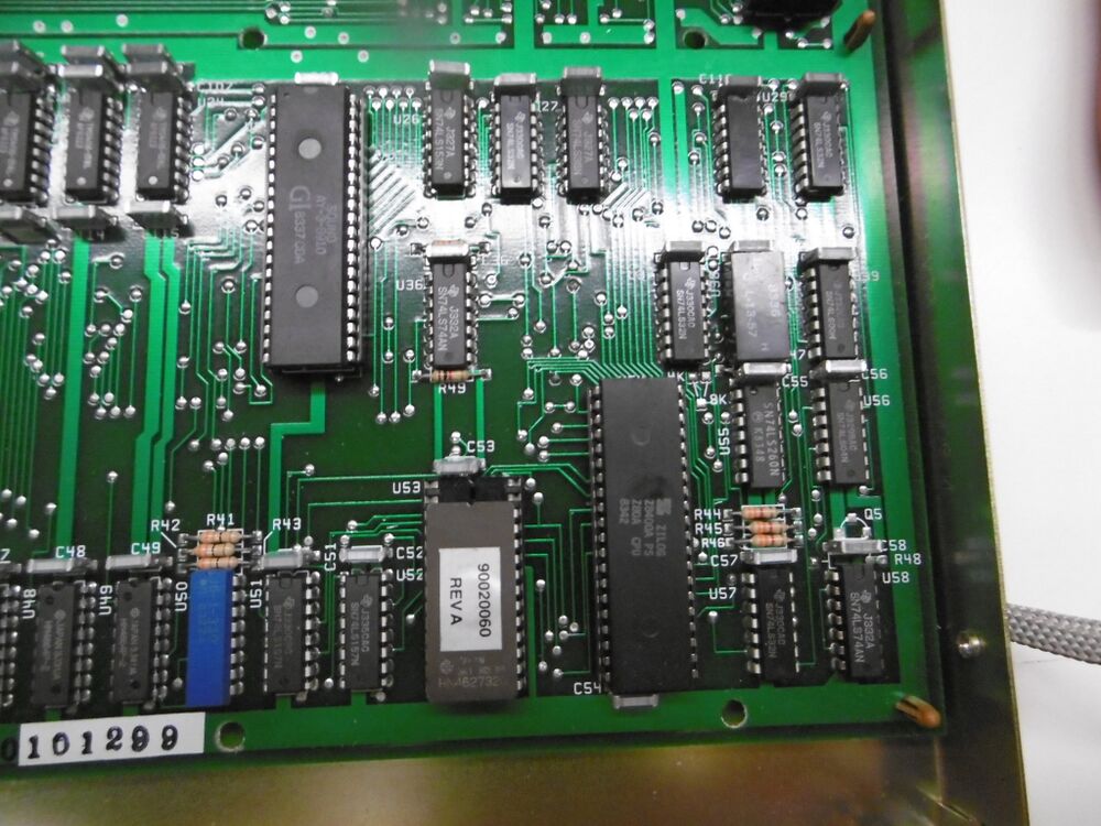
On the bottom right quart we find the Z80A CPU, and the AY-3-8910 programable sound generator.
we also find a tiny EEPROM that contains the BIOS, and boot code through the RS485 cable modem connection. the bottom left shows some 64K x 1 bit RAM chips type HM4864 a resistor pack, and some multiplexers for DRAM. the bottom left quart shows more DRAM chips, with the 8th chip being of a different type from the rest, as an MCM6665, also an 64K x 1-bit DRAM.
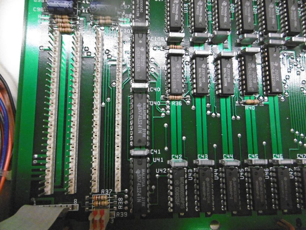
But the most obvious detail is the four strips of pinheaders. These are the I/O expansion "slots", for the four I/O devices, each having its own connector backplate on the back of the NABU.
The NABU assigns a short range of Z80 I/O addresses to each strip, for easy I/O expansion, probably for a floppy drive controller or other I/O.
note that the most left of the 64K DRAM chips is different from all the others, a Motorola MCM6665 instead of the seven Hitachi HM4864P! But thats just a coincidence, the NABU of my friend (Frank) has eight of these HM4864P chips, and none of the Motorola ones. Unfortunately when he boots his NABU he gets a whole load of error codes on his screen, and apparently these indicate some kind of RAM errors!
Socketing the 64K x 1 DRAM chips of a NABU
So on Franks request I removed the PCB from his NABU, this was quite difficult, as the plastic standoffs were hard to get loose, and you also have to unscrew the LED board, as it is soldered via a piece of rigid flat-cable to the PCB. Otherwise its just unscrewing the three screws on the back side of the PCB then pressing in the tabs of the plastic standoffs starting from the front and then slowly lifting up the PCB, this worked with all standoffs except one which I decided to cut off from the bottom, it stayed pushed into the PCB and wouldn't budge.
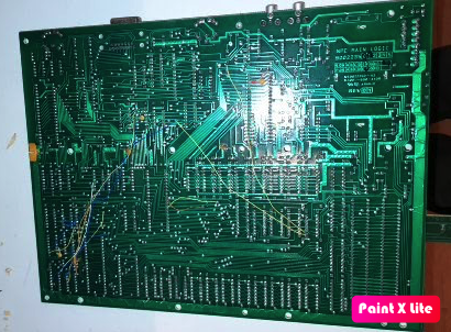
When I had removed the PCB, (I cut of the eight power wires, they will be reconnected with a MOLEX connector set, similar to the one right next to the power leads, but one with more pins) I found out that there were a dozen or so patchwork wires crisscrossing the bottom of the PCB, so probably the first attempt of designing the PCB had many errors.
underside of NABU PCB:
there were patch-wires crossing the row of 16K DRAM chips, but luckily not the 64K DRAM chips, as my task was to desolder the DRAM's, and put in (dual wipe) sockets instead.
Easier said than done, but luckily the PCB was old style (solder that gets under the solder mask makes for a very rippled surface on the copper planes) but other wise the PCB was of very good quality, so desoldering went okay, without damaging the traces. It is just a lot of work with the desoldering iron (I did not use solder-wick, only plenty of flux).
So now I have socketed the Z80's DRAM, and hopefully that will help to resolve the RAM errors, Frans can now test the chips in his ram tester (he has both the universal retro chip tester, and the small but efficient MiniPro TL866, (although that one can only test static RAMS if i remember correctly). Anyway Frans has the possibility to take out a DRAM chip and test it.
Then after buying the 8-pin male Molex style connector and creating an 8-pin female plug, he can power up his NABU again. I have no idea why there are four GND wires, I think one (or maybe two) should be enough. It seems the NABU is somewhat over-engineered.
And yes, the new power supply must also provide -12V not only +12V, as there is a simple zener dropper circuit on board to supply -5V to the TMS4116 DRAM chips for the VRAM of the TMS 9918A video chip. Otherwise -12V is only used for the I/O expander pinheaders. See page 16 of the Nabu_Computer_Technical_Manual_by_MJP. Luckily the new PSU I now also have (a mean well RT-65) provides +12V and -12V, and 5A of +5V. twice the amount of the original PSU! I also have a new 220V low noise FAN, and a new power (mains) connector. Which I will built into my NABU tomorrow during the RevSpaces open day.
buying an RS422 adapter
I still have to order a suitable RS422 USB adapter. Ill make sure it is terminated with 180 Ohm on the receive channel, I presume there are many NABU users that don't know this is necessary with RS422, and they will have a unreliable connection as a result! You should also connect it to the 5-pin DIN using two twisted wire pairs! grounding the RS422 adapter to the NABU is POINTLESS as the DIN-5 connector does not have a GND pin! Which is also clear from the schematic. Make sure to buy a well designed USB adapter using a real FTDI chip, Chinese junk with fake chips will not work well here.
Built in new FAN and PSU
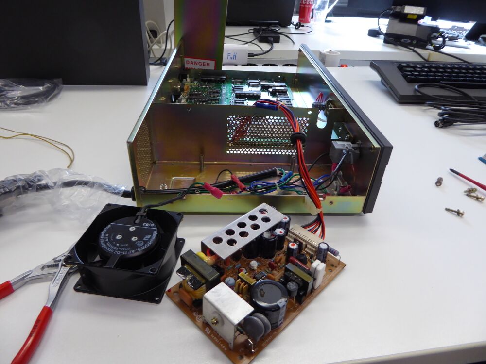
I disassembled the FAN and the PSU
I made notes what the colors of the low voltage wires are.
Black is GND, Gray = +12V, RED = +5V and blue = -12V.
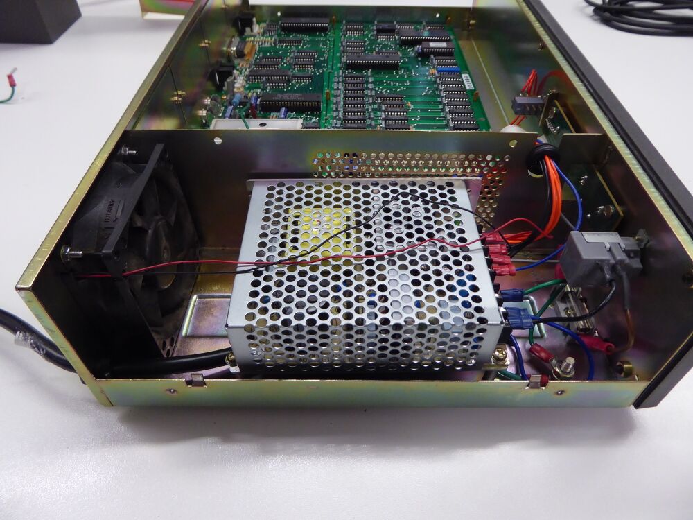
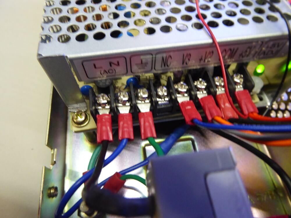
Mounting the (+5V) fan was not too bad, and to mount the new meanwell 220V 50Hz PSU I only needed to drill out one of the 3mm screwholes with a 4mm drill, then I could use the original screws.
This is the result after building in a new fan and the new PSU.
First test
When I turned on the NABU the fan started to run, and the power up sequence appeared correctly. It works!
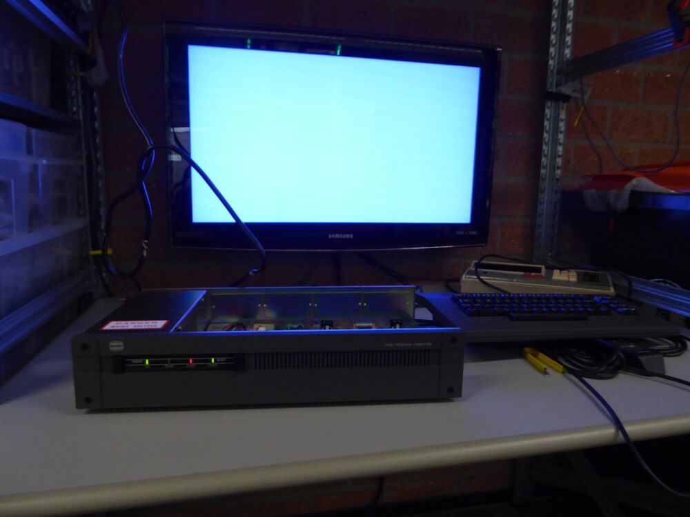
Next I connected up a modern SAMSUNG TV. All modern TV's support displaying bot PAl and NTSC video, so no problem there! Only the screen I got was completely empty! It displayed the normal NABU purple/blue color, but neither the "waterfall" GPU test nor any kind of text.
I determined that the Z80 CPU ran because if I pressed the reset button, and then turned the NABU then the screen stayed black until I released the reset button.
So after some thinking and measuring I found the cause, the 16K DRAM chips TMS4116, are of an older type that require three power supply voltages, pin 1 -5V, pin 8 +12V pin 9 +5V and pin 16 GND. In this case the +12V was absent (measured -5V)! The +12V is also used for the 10Ohm 5 Watt dropper resistor to convert keyboard power to +8 (or +9, schematic has an error in that regard) and there +12V was present, but not on the RAMś, and not on the LM3900 audio mixer chip U15. But there was connection between the 12V pins of the RAM's and the LM3900. So I now suspect a break somewhere in the PCB, or perhaps a broken patch-wire.
Next week I will look for the break, after I have had a look on the NABU PCB that was disassembled (Franks NABU).
Found the problem!
with the use of the other NABU PCB, where I could see the underside of the PCB, the mystery was finally resolved. There happen to be two different +12V power connections! One is used only for the keyboard power, though the large 10 Ohm 5 Watt resistor (which seems to be added as an afterthought) it drops the +12V to +8 or 9 Volt (the schematic calls this voltage 8 Volt at one place and 9 volt at another which is early a surprise for hand drawn schematics, before the use of CAD systems). And there is another seperate +12V input that is used by the LM3900 and the TMS4116 VDRAM (and the GPIO pinheaders)
so when looking at the power connector, the order is
Pin 1 is for GND Pin 2 is also for GND Pin 3 is not used! Pin 4 is also for GND Pin 5 is used for +12V for the keyboard, through a 10 Ohm resistor that drops the +12V to a less taxing +8V for the (LM7805) regulator in the keyboard. Pin 6 is used for +5 Volt, so for all logic etc. Pin 7 is used for +12 Volt for the TMS4116 VDRAM and the LM3900 (and the GPIO headers) Pin 8 is used for -12V through a zener circuit (R30, C99 and Zener CR2) it creates -5V also for the TMS4116, and also -12V for the GPIO headers.
so next time I will correct the wiring, and try again.
NABU is working!
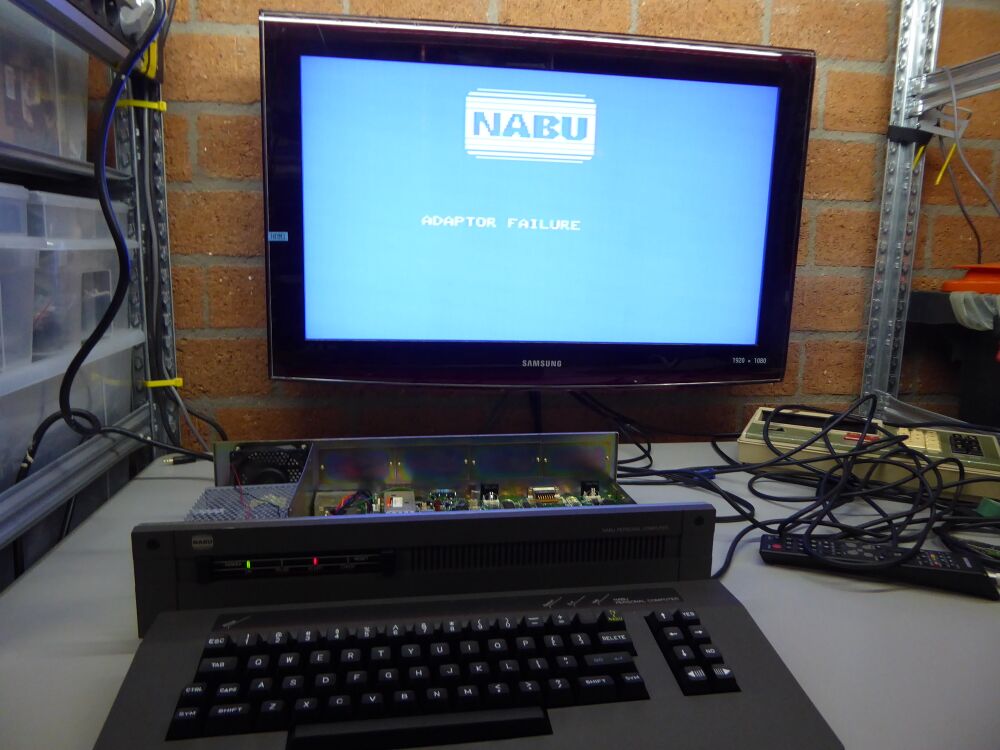
Its working!
I was also advised to re-do the cable lugs as I used the crimping tool the wrong way, and should have used only the RED lugs. So I did all of them again, and used orange wire for the +12V for the TMS4116, and grey for the +12V for the keyboard. Oh and red (which I could just distinguish from orange) for the +5V, blue for -12V and obviously black for GND (3x)
