Assembling RhoCoCo: Difference between revisions
No edit summary |
No edit summary |
||
| Line 22: | Line 22: | ||
Next up was soldering the SD-card holder, as I was already afraid of, the card holder had two plastic pins, I had designed no holes for in the PCB. The datasheet of the card holder was very fuzzy about these two pins, and I could not determine if they really existed, and exactly where they were located. Easy solution was to cut the pins off. Fortunately all the other (solder) pins I seemed to had placed correctly. | Next up was soldering the SD-card holder, as I was already afraid of, the card holder had two plastic pins, I had designed no holes for in the PCB. The datasheet of the card holder was very fuzzy about these two pins, and I could not determine if they really existed, and exactly where they were located. Easy solution was to cut the pins off. Fortunately all the other (solder) pins I seemed to had placed correctly. | ||
This is the PCB, with only the card reader soldered to it, in the back you can see the component overview drawing, | This is the PCB, with only the card reader soldered to it, in the back you can see the component overview drawing, with R1 marked as placed. | ||
[[File:IMG 20190330 212947.jpg|800px]] | [[File:IMG 20190330 212947.jpg|800px]] | ||
You can also see resistor R1 in this picture, and that it only just fits, with its leads bent straight at the body of the resistor. | You can also see a resistor (R1) in this picture, and that it only just fits, with its leads bent straight at the body of the resistor. All resistors I used were designed with 3/10" pitch, for the smallest possible footprint with classic 1/4Watt resistors. | ||
Then I started soldering the resistors, here you can see the 240 Ohm resistors, before soldering, legs bent outwards a bit to keep them in place for soldering. | Then I started soldering the resistors, here you can see the 240 Ohm resistors, before soldering, legs bent outwards a bit to keep them in place for soldering. its best to start with resistors, so you can lay the board flat on its back with resistors being pushed al the way trough the PCB because no higher components are yet placed. That is the reason we always start with the lowest profile parts first. | ||
[[File:IMG 20190330 213317.jpg|800px]] | [[File:IMG 20190330 213317.jpg|800px]] | ||
After the axial resistors, I dd the resistor pack, noting the dot (pin-1 mark) to correspond to the pin-1 mark on the PCB, then I continued with the diodes. | |||
Diodes are not minimally spaced as bending the leads very close to the glass might break the glass, so I hold the diode between thumb and forefinger and fold the wire with the nail of my thumb resting on the wire, just past the glass, Then I did the socket strips for the keyboard, and all IC sockets. Notice the sockets are all oriented the same way, except for the | |||
So after an evening, I had done all resistors, the resistor pack, diodes, socket strips, and all IC sockets. I soldered the same kind of socket strips that were on the PCB to the end of the connector strips, as the wire ends were too thin to make good contact with the sockets. Luckily I had anticipated this, and bought some extra socket strips for this purpose. | So after an evening, I had done all resistors, the resistor pack, diodes, socket strips, and all IC sockets. I soldered the same kind of socket strips that were on the PCB to the end of the connector strips, as the wire ends were too thin to make good contact with the sockets. Luckily I had anticipated this, and bought some extra socket strips for this purpose. | ||
Revision as of 15:21, 31 March 2019
| Project Assembling a RhoCoCo home computer | |
|---|---|
| |
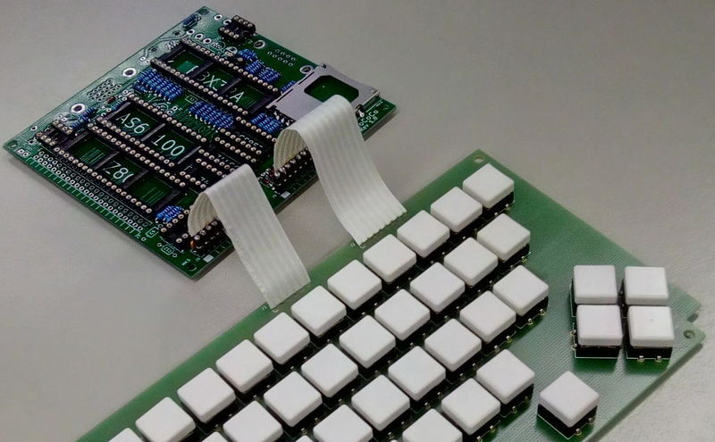
| This text describes how to assemble a RhoCoCo home computer from two PCB's, ten (socketed) integrated circuits, a dozen connectors and various other parts. | |
| Status | Initializing |
| Contact | Mahjongg |
| Last Update | 2019-03-31 |
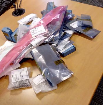
We need, two PCB's, the parts from this list: File:RHOCOCO rev 1.8 assembly list.pdf
a soldering iron, and this assembly drawing to locate each part. File:Rhococo rev 1.8 component overview.pdf
In principle we start by soldering the only SMT part to the PCB, the SD-card-connector, this might have been pre-assembled for you. Then we do the resistors, and the diodes by bending them into shape.
I practice I decided I wanted to build up the keyboard first, but quickly ran up to a problem, all the holes in the keyboard PCB for the keys were too small (smaller than 1mm) to fit the pins of the keys through, and I had to drill all 400 holes with a 1.5mm drill (through a stack of three PCB's). I should have checked if the hole size of this library footprint was correct.
Then I soldered 49 keys, and two connector strips to the PCB's.
This is the result: 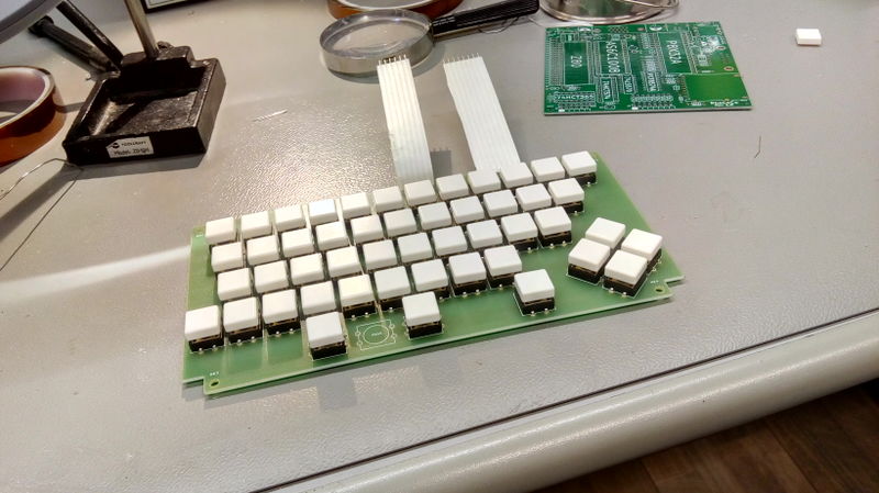 .
.
Farnell only delivered 49 keys, not 50, so I left the middle of the three-key spacebar out for now.
Next up was soldering the SD-card holder, as I was already afraid of, the card holder had two plastic pins, I had designed no holes for in the PCB. The datasheet of the card holder was very fuzzy about these two pins, and I could not determine if they really existed, and exactly where they were located. Easy solution was to cut the pins off. Fortunately all the other (solder) pins I seemed to had placed correctly.
This is the PCB, with only the card reader soldered to it, in the back you can see the component overview drawing, with R1 marked as placed.
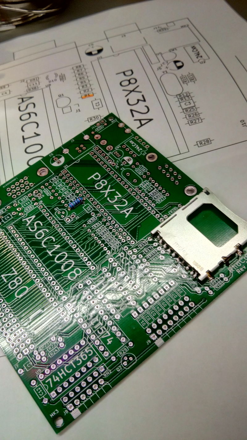
You can also see a resistor (R1) in this picture, and that it only just fits, with its leads bent straight at the body of the resistor. All resistors I used were designed with 3/10" pitch, for the smallest possible footprint with classic 1/4Watt resistors.
Then I started soldering the resistors, here you can see the 240 Ohm resistors, before soldering, legs bent outwards a bit to keep them in place for soldering. its best to start with resistors, so you can lay the board flat on its back with resistors being pushed al the way trough the PCB because no higher components are yet placed. That is the reason we always start with the lowest profile parts first.
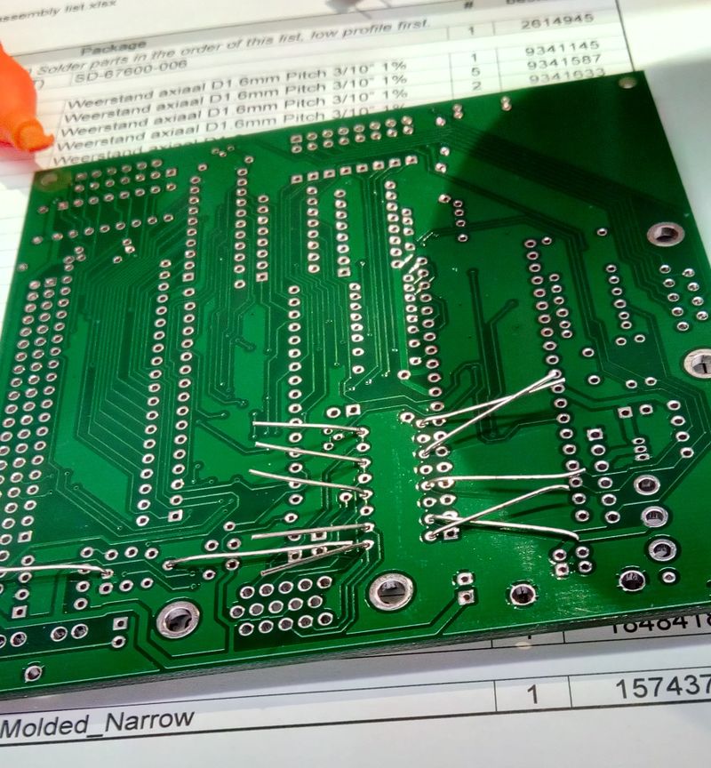
After the axial resistors, I dd the resistor pack, noting the dot (pin-1 mark) to correspond to the pin-1 mark on the PCB, then I continued with the diodes. Diodes are not minimally spaced as bending the leads very close to the glass might break the glass, so I hold the diode between thumb and forefinger and fold the wire with the nail of my thumb resting on the wire, just past the glass, Then I did the socket strips for the keyboard, and all IC sockets. Notice the sockets are all oriented the same way, except for the
So after an evening, I had done all resistors, the resistor pack, diodes, socket strips, and all IC sockets. I soldered the same kind of socket strips that were on the PCB to the end of the connector strips, as the wire ends were too thin to make good contact with the sockets. Luckily I had anticipated this, and bought some extra socket strips for this purpose.
I also used to socket strip sockets to create a holder for the crystal, so that I could easily replace the crystal if its frequency has to change.
This is what I had at the end of the evening:
